Timer And Contactor R Relay Diagram - Electrical Diagrams Clock Timer Contactor Ladder 4 Wires Esquemas Electricos Esquemas Electricidad Industrial. 1 master element 2 time delay starting or closing relay 3 checking or interlocking relay 4 master contactor 5 stopping device 6 starting circuit breaker 7 rate of change relay 8 control power disconnecting device 9 reversing device 10 unit sequence switch 11. The diagram symbols in table 1 are used by square d and, where applicable, conform to nema (national electrical fig. 147 (15 gn) for 11 ms internal ram: Nrnt_nrnt7_e173076_timer new nfc timer renf22r2mmw. A 12v relay is used to drive the ac load connected at the output.
Obtaining from factor a to point b. 147 (15 gn) for 11 ms internal ram: Time delay relay schematic symbol. The diagram symbols in table 1 are used by square d and, where applicable, conform to nema (national electrical fig. Thus relay will be on for required amount of time set by the user using pot and then it is switched of automatically.
Timer Switch Control Start And Stop By Relay Timer Youtube from i.ytimg.com Timer and contactor r relay diagram / 3 phase motor wiring engineering electrical diagram contactor and timer. The contactor relay contacts themselves constitute a considerable safety feature. 147 (15 gn) for 11 ms internal ram: Class 9999 type xtd and xte. Timer and contactor wiring diagram pdf. Hence time t=120k*470uf=6 2 seconds~1 minute (approximately). Obtaining from factor a to point b. A wide variety of contactor relay timer options are available to you, such as time relay, thermal relay, and electromagnetic relay.
Time delay relay schematic symbol.
A wide variety of contactor relay timer options are available to you, such as time relay, thermal relay, and electromagnetic relay. I am looking to build a circuit that would control an output relay. Relays are switches that open and close circuits electromechanically or electronically. Timer and contactor r relay diagram : 240 volts ac and 480 volts ac are commonly used for these large pieces of. View and download cecilware cl200 n operation manual online. Literally, a circuit is the path that permits electrical energy to. Smallest size (10.2 × 18.2 × 14.8 mm) at 10a. Each relay activation will cause the light to toggle. Contactor switching time is higher than relay. A contactor joins 2 poles together, without a common circuit between them, while a relay has a common contact that connects to a neutral position. Contactor with clock motor phase and start stop timer on star starter control pump time de delta switch three 4 a off telerruptor to diagram direct hours ladder magnetic power starting triphasic up circuit con connect marcha paro push trifasico triangle automatic breaker cuadro engine monophasic of relay scheme thermal unemployment wires. Single phase contactor wiring diagram with timer.
Time delay relay schematic symbol. Timer and contactor r relay diagram : The lights stay on after parking car, and then. Contactor switching time is higher than relay. A normally open relay will switch power on for a circuit when the coil is activated.
St3p On Delay Timer Alion from www.aliontimer.com 8 pin relay electric relay electric relays principles. It has multiple transistors and relay outputs. Time delay relay schematic symbol. This sample is particularly useful since you can replace one relay (as shown in the diagram) with a physical light switch. Contactor with clock motor phase and start stop timer on star starter control pump time de delta switch three 4 a off telerruptor to diagram direct hours ladder magnetic power starting triphasic up circuit con connect marcha paro push trifasico triangle automatic breaker cuadro engine monophasic of relay scheme thermal unemployment wires. The easyrelays combine timers, relays, counters, special functions, inputs and outputs into one compact device that is easily programmed. Contactor switching time is higher than relay. Abbs motor protection and control offering is among the widest on the market.
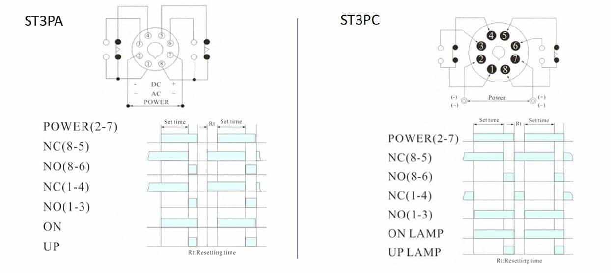
8 pin relay electric relay electric relays principles.
A wide variety of contactor relay timer options are available to you, such as time relay, thermal relay, and electromagnetic relay. Class 9999 type xtd and xte. Relays control one electrical circuit by opening and closing contacts in another circuit. Operationally, it works the same way. Contactor switching time is higher than relay. Contactor switching time is higher than relay. Relays are switches that open and close circuits electromechanically or electronically. Timer and contactor r relay diagram : View and download cecilware cl200 n operation manual online. Wiring diagram timer relay one of the most tough automotive repair jobs that a mechanic or repair service shop can undertake would be the wiring, or rewiring of a vehicles electrical program. I am looking to build a circuit that would control an output relay. The relays tent to be smaller originally answered: As relay diagrams show, when a relay contact is normally open (no), there is an open contact when the relay is not energized.
Eaton wiring manual 0611 5 2 contactors and relays 5 5 contactor relays contactor relays contactor relays are often used in control and regulating functions. Timer and contactor wiring diagram pdf. The contactor relay contacts themselves constitute a considerable safety feature. As relay diagrams show, when a relay contact is normally open (no), there is an open contact when the relay is not energized. Legacy schneider electric™ time delay and sensor relays provide cost effective solutions for your industrial timing and sensing needs.
Timer And Contactor R Relay Diagram Service Technician Training Electricity For Servicepeople Part 22 Cleaner Times In Large Hydroponic Systems Being Able To Time Control Multiple Leggsweir from i0.wp.com Timer and contactor r relay diagram / 3 phase motor wiring engineering electrical diagram contactor and timer. Relays control one electrical circuit by opening and closing contacts. Use these tips to learn how to wire a contactor. Since 1946 ise is the preferred source for timers and controls for industry. Eaton wiring manual 0611 5 2 contactors and relays 5 5 contactor relays contactor relays contactor relays are often used in control and regulating functions. Literally, a circuit is the path that permits electrical energy to. Core features for timing relays. Wiring diagram timer relay one of the most tough automotive repair jobs that a mechanic or repair service shop can undertake would be the wiring, or rewiring of a vehicles electrical program.
Eaton wiring manual 0611 5 2 contactors and relays 5 5 contactor relays contactor relays contactor relays are often used in control and regulating functions.
Operationally, it works the same way. 147 (15 gn) for 11 ms internal ram: Switching two relays at one time is like flipping 2 switches at once….with the same result. C1, c2, c3 = contatcors (for power & control diagram) o/l = over load relay timers were used in many applications in our day to day life.one can see the timers in washing machines,micro ovens etc. The 555 timer, designed by hans camenzind in 1971. Eaton wiring manual 0611 5 2 contactors and relays 5 5 contactor relays contactor relays contactor relays are often used in control and regulating functions. A = off delay : A very first check out a circuit representation may be confusing, however if you can read a train map, you can review schematics. A 12v relay is used to drive the ac load connected at the output. 1 master element 2 time delay starting or closing relay 3 checking or interlocking relay 4 master contactor 5 stopping device 6 starting circuit breaker 7 rate of change relay 8 control power disconnecting device 9 reversing device 10 unit sequence switch 11. The relays tent to be smaller originally answered: Adjusting the delay time is often as simple as turning a knob. Control input s on activates output r.